
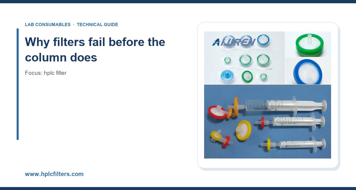
I still remember the Monday morning a production HPLC went flat at 9:40 AM. The autosampler had injected 38 samples overnight, the pump pressure was down 40 bar from Friday, and the peak shapes looked like a bad sketch. The culprit was a $0.60 inlet filter frit that had been in service for 11 weeks. I pulled the logbook and found that the same column had been running a mobile phase with 20 mM phosphate buffer at pH 6.8 and no inline filter ahead of the guard. That single failure cost about six hours of instrument time and a rerun of 38 samples. Since then I have tracked filter failures across our lab and our customers’ labs, and the pattern is consistent: most “filter failures” are not filter defects. They are system design, handling, or maintenance problems that show up at the filter because that is where the smallest orifice in the flow path sits.
A typical analytical HPLC filter is a sintered stainless steel or titanium frit, or a polymeric membrane disc, with a pore rating between 0.2 µm and 2 µm and a diameter between 2 mm and 4.6 mm for inline use. The pressure drop across a clean 0.5 µm frit at 1.0 mL/min of water is on the order of 1 to 3 bar. That number is small compared with the 80 to 400 bar a modern column generates. The problem is that the filter has an open area maybe 30 to 60 percent of its face, and every particle larger than the pore rating lands on that face and stays there. A 2 µm particle captured on a 0.5 µm frit does not pass through. It builds a cake.
Particle cake is the dominant failure mode. As cake thickness grows, the effective pore size shrinks and the pressure drop rises roughly with the square of flow rate and linearly with cake thickness for laminar flow through a porous bed. In practice, a filter that starts at 2 bar can hit 30 bar in a few hundred injections if the sample is dirty. When the pressure drop exceeds the pump’s ability to control flow, retention times drift, peak areas fall, and eventually the system faults out. I have seen gradient baselines roll upward for two days before anyone checked the inlet frit.
The second failure mode is chemical. Buffers at pH above 7 attack borosilicate frits and, more slowly, some stainless grades. Phosphate buffers can precipitate when mixed with high-organic mobile phases, and the precipitate forms exactly where the local solvent composition shifts, which is often inside the filter housing. The third mode is mechanical: over-torqued fittings crack frit rims, and repeated wrenching on a 1/16 inch fitting with a 1/4 inch wrench puts bending stress on the filter body. The fourth is microbial growth in aqueous mobile phases left standing over a weekend. Biofilm does not care that your frit is 0.2 µm rated. It grows through and around the seal.
The failure modes I see most, ranked by frequency
1. Plugged inlet frit from unfiltered sample
This is the number one cause in our logs, accounting for roughly 45 percent of filter-related service calls. Samples prepared by simple dilution and vortexing, without centrifugation or syringe filtration, carry particulates in the 1 to 50 µm range. A 0.45 µm syringe filter removes most of them, but only if the sample is actually pushed through one. I have watched analysts load a turbid sample directly into a vial insert and wonder why the column inlet frit turns brown after 200 injections.
The fix is procedural, not hardware. Centrifuge at 10,000 to 14,000 × g for 5 minutes before transfer, or push through a 0.22 µm or 0.45 µm membrane. Use a PTFE membrane filter for aggressive solvents and a regenerated cellulose or nylon membrane for aqueous samples. PTFE is chemically inert and compatible with nearly every HPLC solvent, which is why we standardize on it for method development.
2. Buffer precipitation inside the frit
Phosphate buffer at 20 to 50 mM is fine in 100 percent aqueous. Mix it with 70 percent acetonitrile and the phosphate can exceed its solubility, especially at low temperature. The precipitate nucleates on the frit face because that is where the mobile phase first contacts a surface with high surface energy. I have cut open frits with a 10 percent white crust that analyzed as sodium phosphate.
Prevention: keep the organic fraction below the precipitation threshold for your buffer, flush the system with 10 percent organic in water before and after any high-organic method, and never leave a buffered mobile phase sitting in the filter housing overnight. A 10-minute flush at 1.0 mL/min with HPLC-grade water after each buffered run adds 10 minutes and saves columns.
3. Seal and ferrule damage from over-torquing
I have a drawer of failed filter bodies with cracked frit rims. Every one came from a fitting tightened with a wrench instead of fingers plus a quarter turn. The specification for a 1/16 inch stainless fitting with a PEEK ferrule is finger-tight plus 1/4 to 1/2 turn. For stainless ferrules, finger-tight plus 3/4 turn is the working rule. Anything beyond that deforms the ferrule and puts radial stress on the filter housing. Torque wrenches exist for a reason: 0.5 to 1.0 N·m is the practical range for most analytical fittings. If you feel resistance beyond that, stop.
4. Microbial growth in aqueous lines
Water purified to 18.2 MΩ·cm is not sterile. Leave a 0.2 µm filter in a water line at room temperature for two weeks and you will grow a biofilm on the upstream face. The biofilm sheds, the frit plugs, and the pressure climbs. I recommend 0.1 percent sodium azide in the water reservoir for systems that sit idle, or a full flush and filter replacement every 7 to 14 days for continuous aqueous use. Never leave a system sitting in pure water for more than 72 hours.
5. Wrong pore size for the application
A 0.2 µm frit is not automatically better than a 2 µm frit. Smaller pores mean higher pressure drop and faster plugging. For a sample with a heavy particulate load, a 2 µm prefilter upstream of a 0.5 µm analytical frit is a better design than a single 0.2 µm frit. I use a two-stage approach on dirty matrices: a 2 µm or 5 µm prefilter at the pump outlet, then a 0.5 µm frit at the column inlet. That arrangement has cut filter replacements by about 60 percent in our environmental methods.
Selection criteria that actually matter
When you specify an HPLC filter, the datasheet lists pore size, diameter, thickness, material, and pressure rating. Those are necessary but not sufficient. Here is the decision checklist I use.
- Pore size: 0.2 µm for UHPLC and sub-2 µm columns; 0.5 µm for standard 3 to 5 µm columns; 2 µm for guard or prefilter positions. Match to the smallest particle you need to remove, not to the smallest pore you can buy.
- Diameter: 2 mm for microbore and capillary; 3 mm for 2.1 mm ID columns; 4.6 mm for 4.6 mm ID columns. An oversized frit adds dead volume. An undersized one adds pressure.
- Material: 316L stainless steel for general use; titanium for high-pH or halide-containing mobile phases; PEEK or PTFE for biocompatible and ion-pairing methods. Borosilicate is fine for pH 2 to 7 but degrades above pH 8.
- Pressure rating: at least 400 bar for HPLC, 1000 bar for UHPLC. Check the rating at temperature, not just at 25 °C.
- Thickness: 1.5 to 3 mm is typical. Thin frits have lower pressure drop but less mechanical strength. Thick frits last longer under particulate load.
- Compatibility: confirm the frit material against your mobile phase pH, salt content, and organic fraction. A compatibility table from the vendor is worth reading before the first injection.
For a full range of inline and precolumn options, the HPLC filter catalog covers pore sizes from 0.1 µm to 10 µm and diameters from 1 mm to 10 mm. I keep a stock of 0.5 µm, 3 mm stainless frits for method development and 0.2 µm, 2 mm PEEK frits for our UHPLC work.
Installation and handling: where most failures are born
I have watched experienced analysts install a filter with bare hands, no gloves, and a wrench. That is three mistakes in one motion. Skin oils and salts transfer to the frit face and create nucleation sites for precipitation. A wrench over-torques the fitting. And no leak check means the first sign of a problem is a pressure spike 200 injections later.
The correct sequence is short. Wear powder-free nitrile gloves. Handle the frit by the rim, never the face. Wet the frit with the mobile phase before installation to displace air from the pores; a dry frit can trap air and cause a pressure spike at first flow. Install finger-tight, then 1/4 turn with a wrench. Run a leak test at 1.5 times the working pressure for 5 minutes. Log the installation date and the injection count on the filter.
That last point is the one most labs skip. A filter with no service log is a filter that fails without warning. I put a small label on every filter housing with the install date and the running injection count. When the count hits the replacement interval, it comes out regardless of how it looks. Preventive replacement beats reactive replacement every time.
Replacement intervals: numbers, not guesses
There is no universal interval, but there are defensible starting points. These come from our service logs and from vendor guidance.
- Inlet frit, clean samples (filtered, aqueous/organic): replace at 1,000 to 2,000 injections or every 3 months, whichever comes first.
- Inlet frit, dirty samples (environmental, food, biological): replace at 200 to 500 injections or every 4 to 6 weeks.
- Solvent inlet frit (in the mobile phase reservoir): replace every 3 to 6 months, and always after changing to a different buffer system.
- Guard cartridge frit: replace with the guard cartridge, typically every 100 to 300 injections.
- Online degasser and pulse damper filters: follow the instrument manufacturer’s schedule, usually 12 months.
These intervals assume the sample is filtered and the mobile phase is degassed and filtered through a 0.2 µm membrane. If either assumption fails, halve the interval. I would rather replace a $0.60 frit every 500 injections than lose a $600 column and a day of work.
A troubleshooting checklist you can run in 20 minutes
When pressure rises or peak shape degrades, work through this list in order. It moves from cheapest to most expensive and from most likely to least likely.
Step 1: isolate the location
Disconnect the column and run water at 1.0 mL/min through the system from pump to detector. If the pressure is above 10 bar with no column, the restriction is upstream: solvent frit, inline filter, or tubing. If pressure is normal without the column but high with it, the column inlet frit is the suspect. This single test saves an hour of guessing.
Step 2: inspect the frit
Remove the frit and look at it under a stereomicroscope at 10× to 40×. Brown or black deposits indicate sample particulate. White crystalline deposits indicate buffer precipitation. A green or blue tint suggests microbial growth or copper corrosion from the pump seals. A cracked rim means mechanical damage from over-torquing.
Step 3: check the mobile phase
Filter a 100 mL aliquot of each mobile phase through a 0.2 µm membrane and inspect the membrane. Any visible residue means the mobile phase is the source. Check the water system’s resistivity and total organic carbon. Water above 5 ppb TOC or below 18.0 MΩ·cm is suspect.
Step 4: check the sample preparation
Centrifuge a sample aliquot at 14,000 × g for 5 minutes and inspect the pellet. A visible pellet means the sample is not clean enough for direct injection. Add a filtration or centrifugation step before the autosampler.
Step 5: check the fittings
Look for ferrule deformation, galling on the threads, and mobile phase weeping at the connection. A 5-minute leak test at 1.5× working pressure will find any seal problem. Replace any ferrule that has been installed more than twice.
Preventive maintenance schedule that works
I run a simple schedule in our lab and recommend it to customers. It is not glamorous, but it keeps filters out of the failure column.
- Daily: check system pressure at the start of the run and compare with the baseline. A rise of more than 10 percent triggers an inspection.
- Weekly: flush aqueous lines with 10 percent organic in water for 10 minutes. Replace solvent reservoir frits if visible discoloration is present.
- Monthly: inspect inline frits under magnification. Log injection counts. Replace any frit above 80 percent of its interval.
- Quarterly: replace inlet frits on all systems running buffered methods. Replace solvent frits. Run a full leak test.
- Annually: replace pump seals, check valve filters, and degasser filters. Review the filter log for trends.
I also keep a spare set of frits for every system in the lab. Downtime waiting for a $0.60 part to ship is the kind of waste that shows up in a cost-per-sample report. The vial insert and consumables inventory should include filters as a line item, not an afterthought.
When the filter is not the problem
About 15 percent of the “filter failures” I investigate turn out to be something else. A partially seized pump check valve produces pressure spikes that look like a plugging frit. A worn rotor seal in the injection valve sheds particles that collect on the frit. A degraded column bed can push fines upstream during backflushing. Before you replace a third frit in a month, check the pump and the injector. The filter is the messenger, not always the cause.
I use a simple rule: if a new frit brings pressure back to baseline, the frit was the problem. If pressure stays high after replacement, the restriction is elsewhere. That test takes 10 minutes and prevents a lot of wasted parts.
Standards and references worth keeping on the shelf
Method development for regulated work should reference the relevant compendial or regulatory guidance. For environmental methods, the U.S. EPA SW-846 test methods describe sample preparation and filtration requirements for waste and materials. For pharmaceutical work, USP general chapters cover chromatographic system suitability and filter compatibility. For instrument-specific guidance, the consumables and column documentation from Agilent and Thermo Fisher is a practical starting point for fitting and frit specifications. Restek technical resources has good application notes on filter and guard selection for specific matrices.
For COD and other water analysis workflows, the sample handling consumables matter as much as the filter. The COD vial selection and the filtration step before digestion both affect the particulate load that reaches the analytical system downstream.
Recommendation: a filter strategy, not a filter part number
If I were setting up a lab tomorrow, I would specify a two-stage filtration strategy on every system. Stage one is a 2 µm or 5 µm prefilter at the pump outlet, sized to the flow rate and rated for at least 400 bar. Stage two is a 0.5 µm frit at the column inlet for standard HPLC, or a 0.2 µm frit for UHPLC. I would standardize on 316L stainless for general methods, PEEK for biocompatible work, and PTFE membrane for sample preparation. I would log every installation with a date and injection count, and I would replace on schedule rather than on failure.
The numbers that matter: 0.2 to 0.5 µm pore size for analytical frits, 2 to 4.6 mm diameter matched to column ID, 400 to 1000 bar pressure rating, 1/4 to 1/2 turn past finger-tight on PEEK ferrules, 10,000 to 14,000 × g for sample centrifugation, and replacement intervals of 200 to 2,000 injections depending on sample cleanliness. Get those right and the filter stops being a failure point and becomes what it should be: a cheap, predictable consumable that protects the expensive parts of the system.
Takeaway: most HPLC filter failures are preventable with three habits. Filter and centrifuge every sample before it reaches the autosampler. Flush buffered mobile phases out of the system before the system sits idle. And replace frits on a logged schedule instead of waiting for a pressure spike. A $0.60 frit is not the place to save money, and a $600 column is not the place to learn that lesson.
References & further reading
Related resources from our lab consumables network:
- Hplc Filter at hplcfilters.com
- Ptfe Membrane Filter at ptfemembranefilter.com
- Cod Vial at codvial.com
- Vial Insert at hplcinsert.com
External references and standards: